Computer Organization and Design 笔记 - The Processor
Introduction
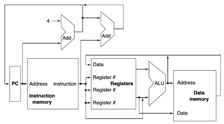
A abstract view of the implementation of the MIPS subset showing the major functional units and the major connections between them:
The basic implementation of the MIPS subset, including the necessary multiplexors and control lines:
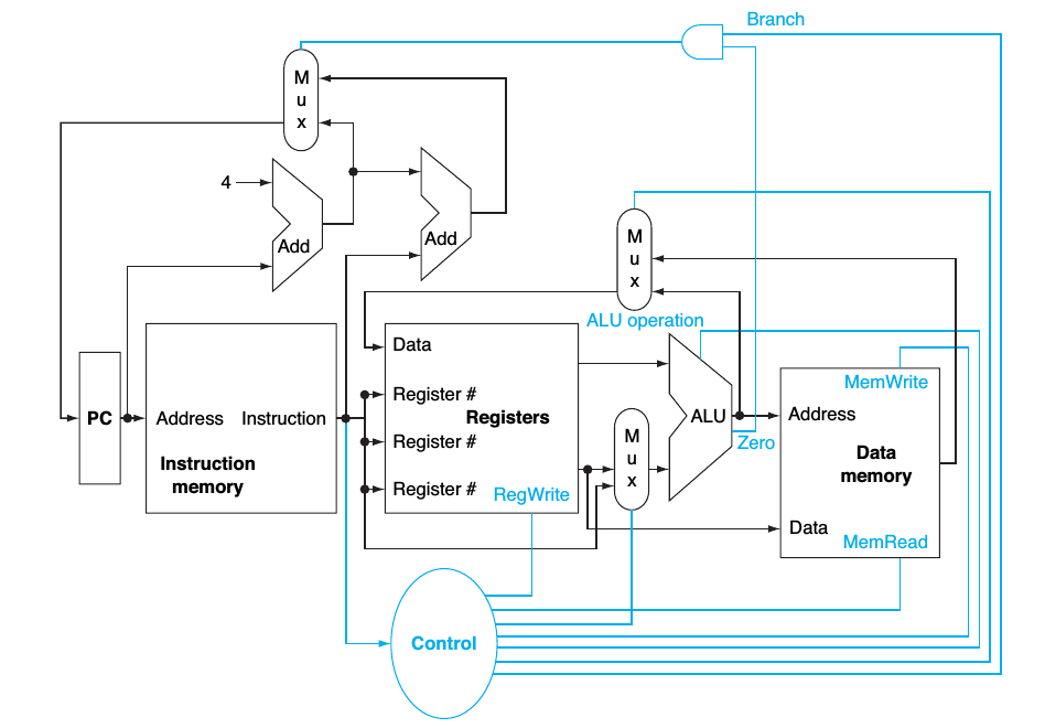
asserted
The signal is logically high or true.
deasserted
The signal is logically low or false.
Clocking methodology
The approach used to determine when data is valid and stable relative to the clock.
Edge-triggered clocking
A clocking scheme in which all state changes occur on a clock edge.
control signal
A signal used for multiplexor selection or for directing the operation of a functional unit; contrasts with a data signal , which contains information that is operated on by a funcional unit.
The state element is changed only when the write control signal is asserted and a clock edge occurs.
A Simple Implementation Scheme
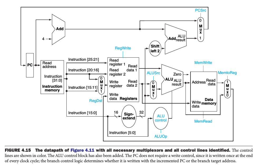
ALUOp indicates whether the operation to be performed should be add for loas and stores, substract for beq, or determined by the operation encoded in the funct field.
Multiple levels of decoding
The main control unit generates the ALUOp bits, which then are used as input to the ALU control that generates the actual signals to control the ALU unit.
The datapath with all necessary multiplexors and all control lines identified:
Single-cycle implementation
Also called single clock cycle implementation. An implementation in which an instruction is executed in one clock cycle.
The clock cycle is determined by the longest possible path in the processor.
An Overview of Pipelining
Assuming ideal conditions:
Time between instructions(pipelined) = Time between instructions(nonpipelined) / Number of pipe states
Pipelining improves performance by increasing instruction throughput, as opposed to decreasing the execution time of an individual instruction, also called latency.
Structual Hazards
When a planned instruction cannot execute in the proper clock cycle because the hardware does not support the combination of instructions that are set to execute.
Data Hazards
Data Hazards occure when the pipeline must be stalled because one step must wait for another to complete.
Control Hazards
Arising from the need to make a decision based on the results of one instruction while others are executing.
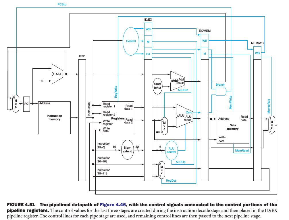
Pipelined Datapath and Control
The datapath is separated into 5 pieces:
- IF: Instruction fetch
- ID: Instruction decode and register file read
- EX: Execution or address calculation
- MEM: Data memory access
- WB: Write back
We can divede the control lines into 5 groups according to the pipeline state
- IF: Signals to read instruction memory and write PC are always asserted, nothing to control.
- ID: As in the previous state, the same thing happens at every clock cycle, no optional control lines to set.
- EX: The signals to be set are RegDst, ALUOp, and ALUSrc. The signals select the Result register, the ALU operation, and either Read data 2 or a sign-extended immediate for the ALU.
- MEM: The control lines set are: Branch, MemRead, and MemWrite. These signals are set by the branch equal, load, and store instructions.
- WB: MemtoReg, which decides between sending the ALU result or the memory value to the register file; Reg Write, which writes the chosen value.
Multiple-clock-cycle pipeline diagram gives overviews of pipelining situations:
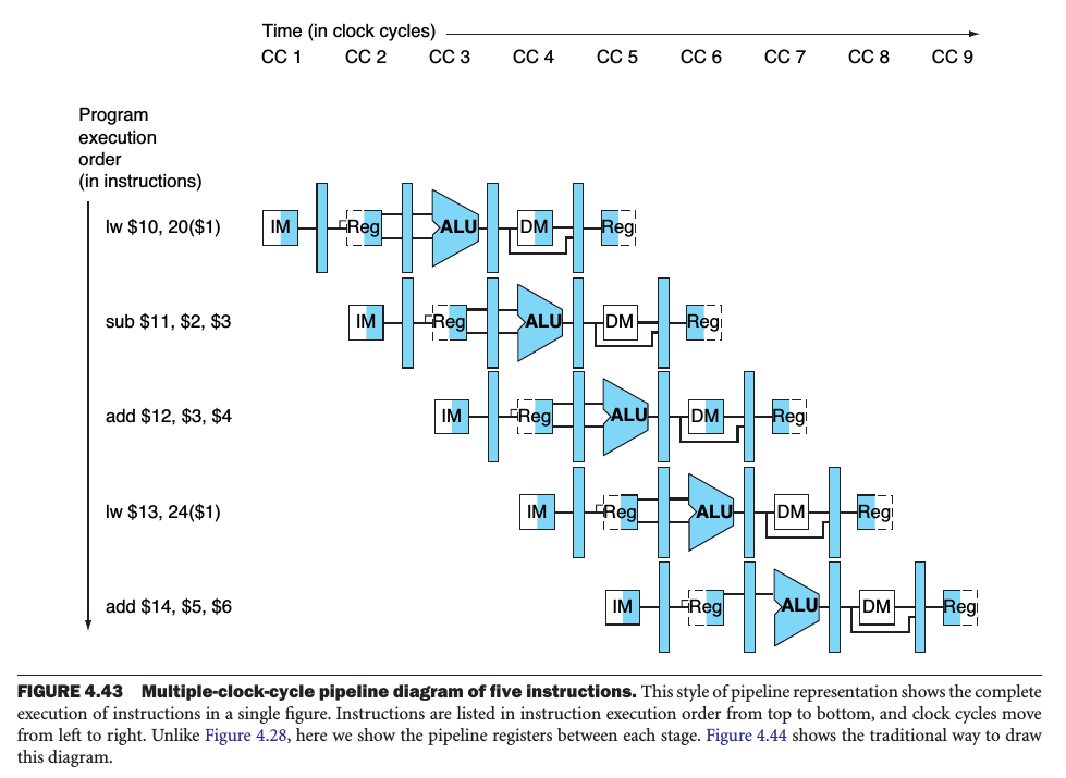
Single-clock-cycle diagram represents a vertical slice through a set of multiple-clock-cycle diagrams, showing the usage of the datapath by each of the instructions in the pipeline at the designated clock cycle.
Data Hazards
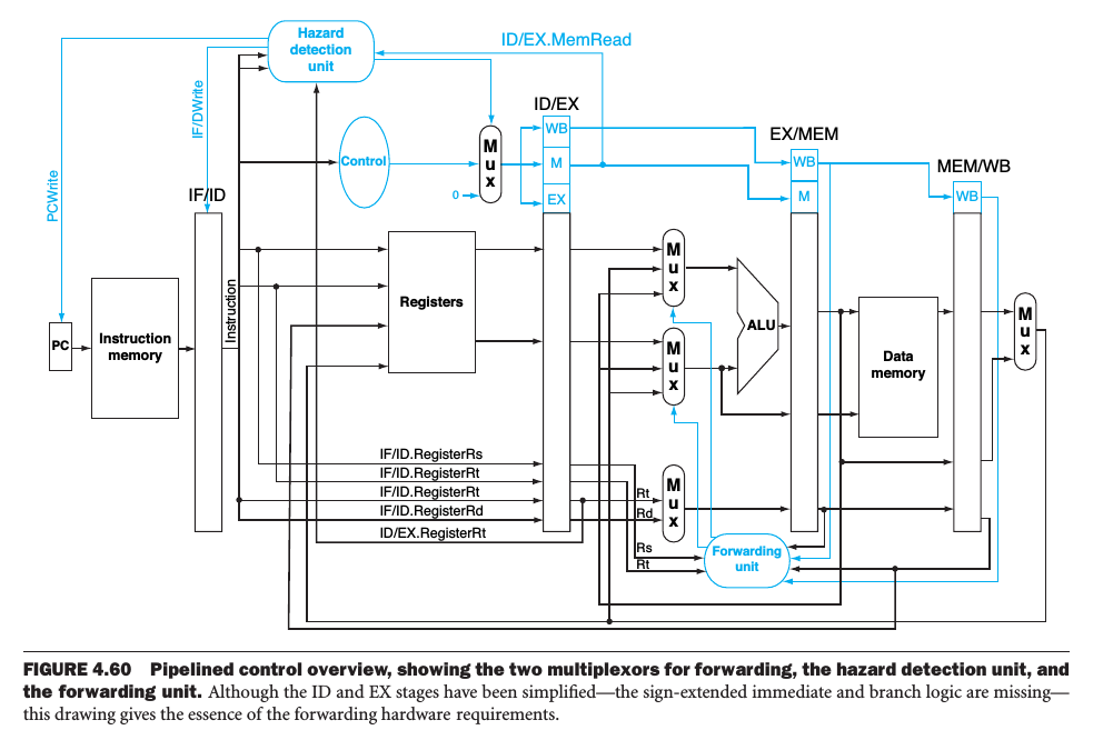
Forwarding
When the result required by the current instruction is computed during EX stage of the previous instruction( or previous previous instruction), forwarding is used. See the two pairs of hazard conditions:
- EX/MEM.RegisterRd = ID/EX.RegisterRs
- EX/MEM.RegisterRd = ID/EX.RegisterRt
- MEM/WB.RegisterRd = ID/EX.RegisterRs
- MEM/WB.RegisterRd = ID/EX.RegisterRt
The forwarding unit is used to forward new values from EX/MEM and MEM/WB pipeline-register to ID/EX pipeline-register when the conditions above occured.
Note that the values in EX/MEM is newer than MEM/WB, we will forward MEM/WB only when EX/MEM needn't to be forwarded.
Stalls
When the result required by the current instruction is computed during MEM stage of the previous instruction, we must stall the pipeline.
The hazard detection unit operates during the ID stage, checking for load instructions and insert the stall between the load and its use. The single condition is:
if( ID/EX.MemRead and
    ((ID/EX.RegisterRt = IF/ID.RegisterRs) or
     (ID/EX.RegisterRt = IF/ID.RegisterRt)))
        stall the pipeline
By identifying the hazard in the ID stage, we can insert a bubble into the pipeline by changing the EX, MEM and WB control fields of the ID/EX pipeline registeer to 0.
Actually, only the signals RegWrite and MemWrite need be 0, while the other control signals can be don't cares.
Control Hazards
Discarding instructions means we must be able to flush instructions in the IF, ID, and EX stages of the pipeline.
Moving the branch decision up requires 2 actions to occur earlier: computing the branch target address and evaluating the branch decision.
Dynamic branch prediction
Prediction of branches at runtime using runtime information.
Dynamic prediction buffer
Also called branch history table , a small memory that is indexed by the lower portion of the branch instruction and that contains one or more bits indicating whether the branch was recently taken or not.
The simple 1-bit prediction scheme has a performance shortcoming: even if a branch is almost always taken, we can predict incorrectly twice, rather than once, when it is not taken.
In a *2-bit scheme**, a prediction must be wrong twice before it is changed.
branch delay slot
The slot directly after a delayed branch instruction, which in the MIPS architecture is filled by an instruction that does not affect the branch.
The delayed branch is a simple solution to control hazards in a 5-stage pipeline. With longer pipelines, superscalar execution, and dymnamic branch prediction, it's now redundant.
branch target buffer
A structure that caches the destination PC or destination instruction for a branch. It's usually organized as a cache with tags, making it more costly than a simple prediction buffer.
correlating predictor
A branch predictor that combines local behavior of a particular branch and global information about the behavior of some recent number of executed branches.
tournament branch predictor
A branch predictor with multiple predictions for each branch and a selection mechanism that chooses which predictor to enable for a given branch.
Exceptions
exception refer to unexpected change internal, while interrupt refer to that external.
MIPS save the address of the offending instruction in the exception program counter (EPC) , and the Cause register holds a field that indicates the reason for the exception.
Vectored interrupt
An interrupt for which the address to which control is transferrd is determined by the cause of the exception.
Exception Procedure
- We must flush the instructions follow the offending instruction from the pipeline.
- Use the EX.Flush signal to prevent the instruction in the EX stage from writing its result in the WB stage.
- Save the address of the offending instruction in the EPC.
Imprecise interrupt
Also called imprecise exception , Interrupts or exceptions in pipelined computers that are not associated with the exact instruction that was the cause of the interrupt or exception.
Precise interrupt
Also called precise exception , An interrupt or exception that is always associated with the correct instruction in pipelined computers.
Parallelism
Instruction-level parallelism (ILP)
The parallelism among instructions.
Multiple issue
A scheme whereby multiple instructions are launched in one clock cycle.
static multiple issue
An approach to implementing a multiple-issue processor where many decisions are made by the compiler before execution.
issue slots
The positions from which instructions could issue in a given block cycle.
Very Long Instruction Word (VLIW)
A style of instruction set architecture that launches many operations that are defined to be independent in a single wide instruction, typically with many separate opcode fields.
A simple 2-issue MIPS processor: one of the instructions can be an integer ALU operation or branch and the other can be a load or store.
Dynamic multiple issue
An approach to implementing a multiple-issue processor where many decisions are made during executino by the processor.
superscalar
An advanced pipelining technique that enables the processor to execute more than one instruction per clock cycle by selecting them during execution.
dynamic pipeline scheduling
Hardware support for reordering the order of instruction execution so as to avoid stalls.
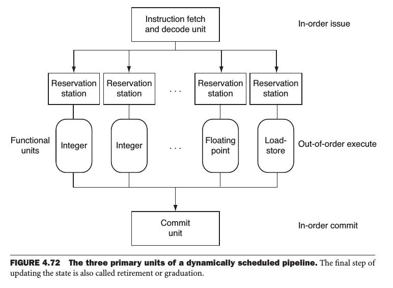
register renaming:
- when a instruction issues, it's copied to a reservation station for the appropriate functional unit.
- If an operand is not in the register file or reorder buffer, it must be waiting to be preduced by a functional unit.
speculation
An approach whereby the compiler or processor guesses the outcome of an instruction to remove it as a dependence in executing other instructions.
In the case of speculation in software, the compiler usually inserts additional instructions that check the accuracy of the speculation and provide a fix-up routine to use when speculation is incorrect.
In hardware speculation, the processor usually buffers the speculative results until it knows they are no longer speculative.
本文采用 知识共享署名 4.0 国际许可协议(CC-BY 4.0)进行许可,转载注明来源即可: https://harttle.land/2014/02/17/computer-design-processor.html。如有疏漏、谬误、侵权请通过评论或 邮件 指出。